Rapid Shutdown Devices and Safety
May 25, 2023
By Thomas Cemo, David Penalva, and James Nagel

Solar PV system fires are rare, dangerous incidents with severe consequences. Regulations that reduce the risk of thermal events obviously make sense. But what if they have unintended consequences?
The HelioVolta team has the combined experience of >500 PV system inspections and dozens of root cause analyses on thermal events. Based on our professional field observations, we believe that the rapid shutdown requirements for PV systems in the U.S. National Electric Code (NEC) have backfired.
Here’s why: every component in a PV system is a potential failure point. The NEC dramatically increased the number of components in residential and C&I systems because module-level power electronics (MLPE) and rapid shutdown devices (RSDs) are the only practical solution for the code’s rapid shutdown requirements.
This article, which is adapted from an article published originally in Solar Builder, covers how the NEC has evolved over time and unintentionally increased the likelihood of PV system fires despite the best efforts of regulators to improve safety. It highlights HelioVolta’s field observations and offers tips for installers to reduce the risk of thermal events.
Understanding PV System Fires
While some PV system fires are publicly documented, many are not. It is extremely hard to gauge how prevalent the failures are. However, we are confident they are extremely rare: solar PV systems are fundamentally safe and reliable when properly installed and maintained.
PV system fires are usually caused by electrical arcing and ground faults that are triggered by loose electrical connections, faulty components, or an electrical pathway between conductors and/or the ground. The fundamental root cause is almost always incorrect installation, improper maintenance, or a manufacturing defect.
The increased use of mass-produced power electronics components over the years has statistically added more failure points to U.S. rooftop solar systems. More failures mean more thermal events. How did we get here?
PV Systems, Safety, and the National Electric Code
Emergency situations can be dangerous and unpredictable. When a fire occurs in or near a PV system, it can damage conduit and create live wires, potentially exposing first responders to harmful levels of DC voltage. Firefighters often break holes in roofs as part of their fire mitigation efforts. The NEC has been updated several times to protect first responders on rooftops with PV systems.
NEC 2014 introduced the first rapid shutdown requirements for PV systems. The updated code aimed to eliminate the risk of first responders encountering DC voltage from PV systems. Here are the details:
- All rooftop PV systems with conductors installed more than 10 ft from the array or 5 ft inside a building required the ability to de-energize below 30 V and 240 VA within 10 seconds of initiating rapid shutdown.
- No additional equipment was required to meet the rapid shutdown requirement if the inverter and all DC conductors were located within 10 ft of the array.
- If DC conductors were located outside the of the 10 ft boundary, it was necessary to install extra equipment for rapid shutdown, such as pass-through disconnects.
Like all updates to NEC, Authorities Having Jurisdiction (AHJs) gradually adopted the 2014 revision. Then in 2017, the NEC upped the rapid shutdown requirement to a 1 ft boundary, modified deenergizing requirements to 80 V or less within 30 seconds, and stipulated three specific conditions for triggering a rapid shutdown: when utility interconnection is disconnected, when the PV system is disconnected, and by a standalone rapid-shutdown switch. This meant that:
- For the vast majority of new PV systems, additional rapid shutdown equipment was now the only way to meet NEC requirements.
- The industry did not have optimal technology solutions for this requirement, but installers still had to react to the code changes.
- The only practical solution was installing MLPE to initiate rapid shutdown at the module level. This increased the number of connections in PV systems.
NEC 2020 then clarified that installers can use one the following three methods to meet rapid shutdown requirements:
- Installing a “PV hazard control system” within the array boundaries.
- Limiting controlled conductors within the array to no more than 80 volts within 30 seconds of rapid shutdown initiation and controlled conductors outside of the array boundary to no more than 30 volts within 30 seconds.
- Installing PV arrays so that they do not have any exposed wiring or conductive parts and are installed more than 8ft from grounded conductive parts or ground.
The Rise of MLPE and RSDs
The evolving rapid shutdown requirements in the NEC dramatically changed the inverter market and the way systems are designed and installed. Inverter market share in residential solar shifted significantly from string inverters to MLPE-based systems – microinverters and power optimizers – from 2013 to 2019, according to the Wood Mackenzie PV Leaderboard. The first MLPE manufacturers to gain traction were Enphase, SolarEdge, and Tigo. Today many inverter manufacturers produce MLPEs, including SMA, Chint, and Sungrow.
The ability of MLPEs to rapidly shut down systems was not a primary function or even a selling point, at least not at first. Power optimizers and microinverters were introduced to bring maximum power point tracking (MPPT) algorithms that control voltage for optimal power output to each individual PV module. String inverters apply MPPT to an entire string, which means that a single shaded PV module reduces the yield of the entire string. MLPE products were primarily developed to overcome these shading challenges, particularly in residential and small commercial rooftop systems.
Largely as a response to NEC 2017, manufacturers developed the rapid shutdown device, a new type of PV system component that enables installers to deploy string inverters and fulfill NEC requirements. Unlike power optimizers and microinverters, RSDs are module-level power electronics with a single purpose: to quickly de-energize PV modules.
Today RSD products are available from many brands, including:
- Tigo
- APSystems
- ZERUN
- Generac
- JMTHY (Note: this product is white-labeled by SMA)
While they look like simple add-ons, RSDs can be tricky to install:
- RSDs are connected directly to PV modules
- There is a precise sequencing of cable connections for each RSD.
- Every connection step must be followed as per manufacturer installation manual.
- There are additional complexities that affect system design and installation to avoid cross-talk or communication problems
- Manufacturers specify limits on the number of RSDs that can be installed in series.
- Each RSDs is only compatible with certain PV modules and inverters – they cannot be mixed and matched universally.
Rapid Shutdown Failures
As we look towards another change to the NEC, it is time to pause and question whether the requirements we’ve implemented thus far are actually accomplishing their mission.
One point of concern is whether 80 V is actually a safe voltage. OSHA defines 50 mA as a potentially lethal current, but only when the current path is through broken skin. Given that firefighters wear a significant amount of personal protective equipment (PPE), a current path through broken skin is very unlikely. So, while it is true that 80 V is safer, we believe the benefits are questionable after factoring in the additional failure points introduced by the rapid shutdown components themselves.
A second point of concern is that, while rare, rapid shutdown system components can cause thermal events, thereby creating more events for firefighters to manage.
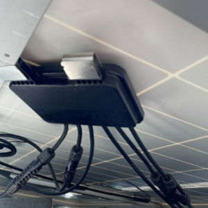
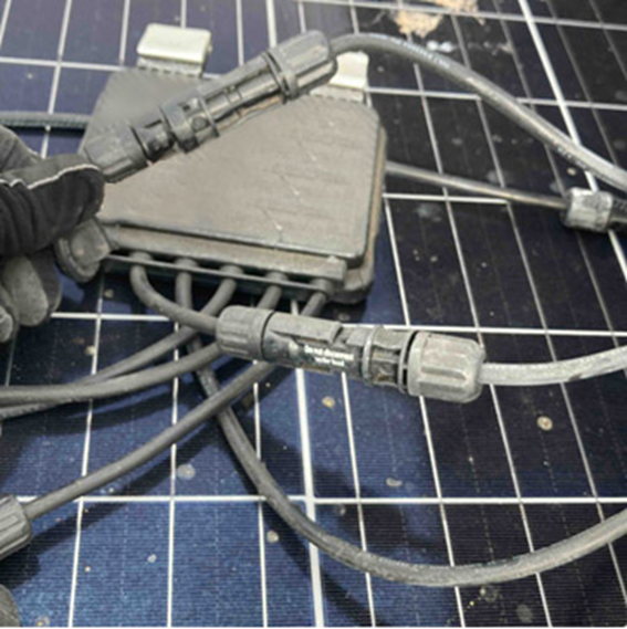
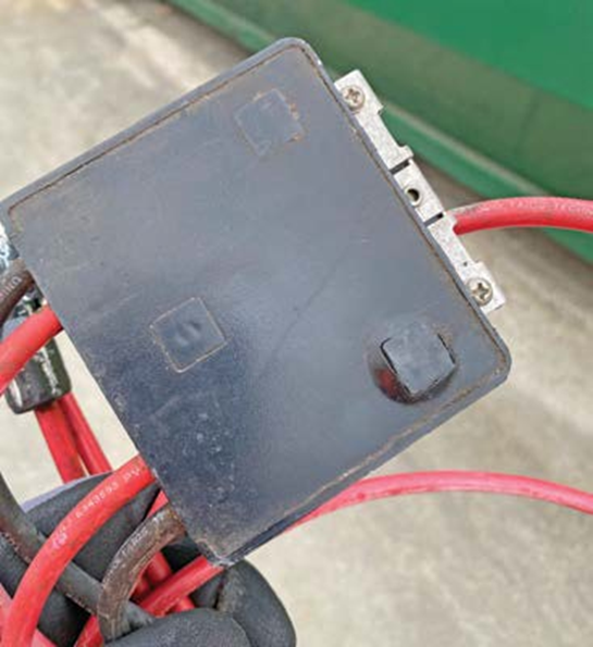
As a third-party PV system auditor, the HelioVolta team has seen evidence of malfunctioning RSDs in system health assessments. The photos throughout this article are just a small sample of problems we commonly see.

The third and biggest issue with RSDs is that they create more connections throughout a PV system. Connector issues are common and still plague the industry – read our Ultimate Safety Guide for Solar Connectors to learn more. Human error must be considered for every field-made connection, even if the right components are used.
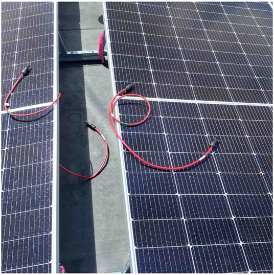
Cross-mating is a huge problem for RSDs as cross-mated connectors introduce incompatibility between tolerances and material. Over time, the mismatch can grow to a hot spot that can only be identified with a thermal camera. NEC 2020 specified that all connectors in a PV system must be made from like parts that are certified to operate as a pair. When RSDs’ connectors are not compatible with the modules’ connectors, jumpers are often used. However well-intentioned, jumpers can still miss the mark due to improper installation.
Occasionally, a failed connector is found during a health assessment inspection that is extremely troubling because it presents the immediate risk of an open circuit condition near the rooftop membrane, as well as the long-term risk of possibly hundreds more like it on the same rooftop.
The good news is that we’ve seen a dramatic increase in stakeholders taking connector issues seriously.
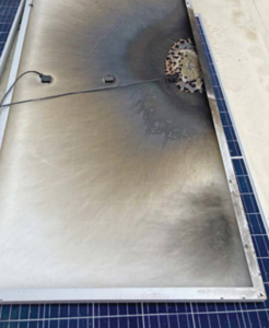
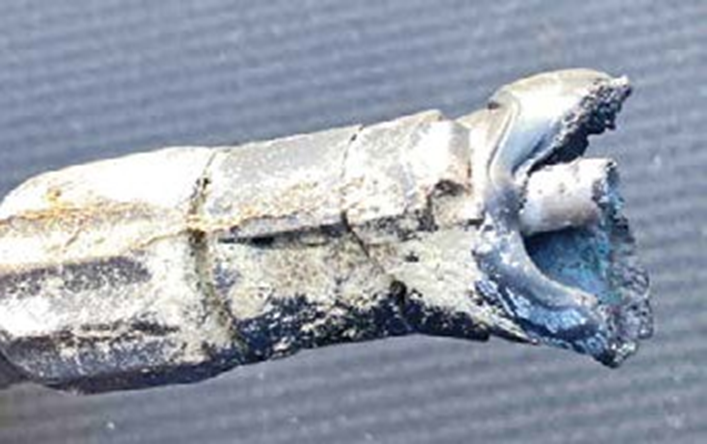
However, failures in rapid shutdown devices are still relatively new and not well understood by many. We’ve had the opportunity to investigate several incidents and better understand the nuances and challenges faced during installation. The photo below shows how the thermal deformation of an RSD caused by overheating can be very subtle and almost indistinguishable. However, when it progresses to the point of failure, it can be catastrophic.
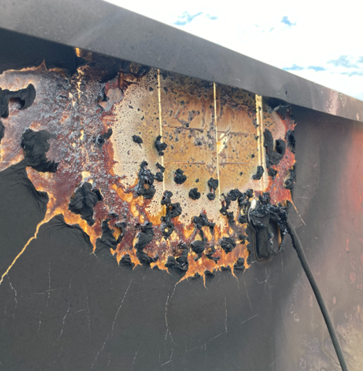
The burn marks on the module below provide some component failure evidence. The exact mechanism of the failure is still unknown and being investigated, however the evidence of the power electronics failing cannot be ignored.
PV system owners and system hosts must emphasize identifying failing components, poor workmanship or incompatible equipment before they become serious risk factors for thermal events.
Supply chain challenges increase risks
The ongoing supply chain difficulties plaguing the solar industry compound the issue at hand. Many times, preferred products or modules are not available, and installers do not know what they will receive until it arrives on-site, or they have to accept what is available. This forces the hand of installers to either wait for the preferred equipment or figure out alternative solutions to get the job completed on time. Typically, projects cannot wait.
Supply chain issues also exacerbate the most common issue for RSD-related thermal events: mismatched PV connectors from the module to the RSD. The 2020 NEC code cycle took this into account by requiring “like connectors,” which should solve the cross-mating problem — but it may create another.
To mitigate potential connector failures from cross-mating, one solution is to use factory-assembled jumpers to ensure that like connectors are mated. However, adding jumpers only increases the number of connectors in the PV system, which then doubles or triples the potential failure points.
Using factory rather than field-assembled jumpers may still be a smart solution because it reduces the variability of making connections on the roof with the wrong tools or inadequate training. However, choosing the right jumper supplier is also a key detail to consider. A “factory-assembled” jumper is often still being manufactured by hand on an assembly line and not by an automated process. This lack of automation can also lead to inconsistent quality control, which can vary from company to company, so jumpers must be purchased from a reputable supplier with strong and reliable QC standards.
The combination of:
1) more complicated equipment in the system
2) increased connection points
3) heavy pressure to keep installed costs low
is a perfect recipe for disaster. Unfortunately, it is a recipe that we have baked into the code.
Solutions
Solutions must be evaluated thoroughly with a high consideration to operational longevity.
Better planning during the design and procurement stage
Engineering and procurement teams need to work closely to specify components that interact with one another are in fact compatible and available. This step seems obvious but is often overlooked or not emphasized. It is a challenging process due to the market dynamics and supply chain constraints coupled with accelerated design schedules. However, it is critical to avoid more complex technical solutions (like jumpers), which add more points of failure.
Improve system monitoring practices and response times.
It typically takes a few days to go from the first warning signs to an actual thermal event. Improving the criteria for alarms related to warning signs can help reduce the risk of fire. Additionally, improving response time once early warning signs are detected is also a key factor. The challenge with this solution is relying more heavily on O&M providers that are monitoring hundreds or thousands of systems simultaneously and the inherent inertia of changing engrained business practices.
If an RSD is going to fail catastrophically, the failure typically occurs within a few days of installation in a typical bathtub curve. Close monitoring soon after system commissioning is vital. However, compromised connectors often take more time to degrade and ultimately fail.
Consider UL 3741 certified equipment that provides a path to eliminate MLPE.
The new certification has its own pros and cons when compared to current solutions. For example, when a system is contiguous, and the inverter can be placed within the array boundary, with certain UL 3741 certified systems, MLPE is not necessary, thus eliminating additional components and connections. However, due to the recent publication of the standard, there are currently few solutions in the market that have been certified.
Current rapid shutdown solutions still have their place with large, distributed arrays when a contiguous design is not possible. However, this evolution in the code and industry provides an opportunity to revisit safety provisions originally proposed by rapid shutdown requirements.
Conduct QA/QC during system construction and/or commissioning
Independent quality control and quality assurance (QA/QC) fieldwork is a valuable tool for PV system owners, operators, and hosts to avoid field failures: reputable inspectors will identify RSD installation issues before they become major problems. HelioVolta provides PV system health checks during construction and after commissioning to validate EPC workmanship. A key output of QA/QC inspections is a punch list of action items that should be addressed by the project’s EPC or O&M provider.
Global examples
The issues we face in the U.S. are not unique. Other countries also face similar challenges. One example is the DC isolator requirement on rooftop systems in Australia that was introduced in 2012 to make systems safer. However, the equipment was prone to water intrusion and often led to fires when the DC contacts were submerged. Fire and Rescue New South Whales’ statistics showed solar PV related fires increased five-fold in the ensuing five years, many attributed to failing DC isolator switches.
The requirement was eventually dropped in late 2021. This highlights the importance of understanding the potential risks and unintended consequences that come with new standards and regulations.
The U.S. solar industry is finding itself in a predicament where following the code that is intended to make PV systems safer statistically adds risk. The industry cannot rely on MLPE as the sole solution for rooftop systems.
Alternate options are required to provide safe and reliable systems that can last their expected 25-year lifespan and deliver on the promises made. UL 3741 is a step in the right direction, providing flexibility in design options.
Next Steps
If you’re an asset owner or host with concerns about RSDs or other PV system components, the HelioVolta team can help.
Contact us to schedule an independent PV system health assessment.
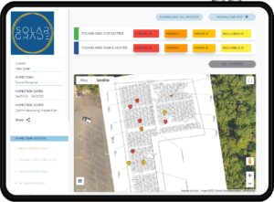
If you regularly install RSDs in rooftop systems, proactive installation QA/QC is important to avoid the risk of future thermal events. Simplify your fieldwork with the SolarGrade platform designed with quality and system reliability in mind for solar professionals by solar professionals.
Schedule a demo to learn how SolarGrade empowers your team to elevate asset care.